
PROJECT · AUTOMOTIVE · LOSS MODELLING
Closing a 30% gap between simulated and measured cycle losses
A customer’s simulation underestimated drive-cycle losses by more than 30%. We found where the missing losses came from and showed how to bring them down.
Sector
Automotive
Customer
[Tier-1 anonymised]
Services
A · Simulation
C · Problem solving
Taurus layers
Magnetic
Performance
>30%
gap between simulated and measured drive-cycle losses
~75%
of that gap traced to PWM-induced copper, iron and magnet losses
01
The challenge
The customer’s CAE model predicted drive-cycle losses more than 30% below what was measured on the test bench. A gap that size undermines every decision built on the model: cooling sizing, switching-frequency strategy and the efficiency margins promised to the vehicle team.
The question was simple: which losses was the model missing, and what could be done about them?
02
Our approach
STEP 1 · TAURUS MAGNETIC
Rebuild the loss model from FEA
Detailed electromagnetic simulation of the machine, without build factors.
STEP 2 · TAURUS PERFORMANCE
Add PWM-induced losses
Copper, iron and magnet losses caused by inverter switching, across the full operating map.
STEP 3 · CORRELATION
Match the measurements
Compare loss by loss against the customer’s test data to locate the gap.
STEP 4 · OPTIMISATION
Define the path forward
Concrete changes to bring the actual losses down.
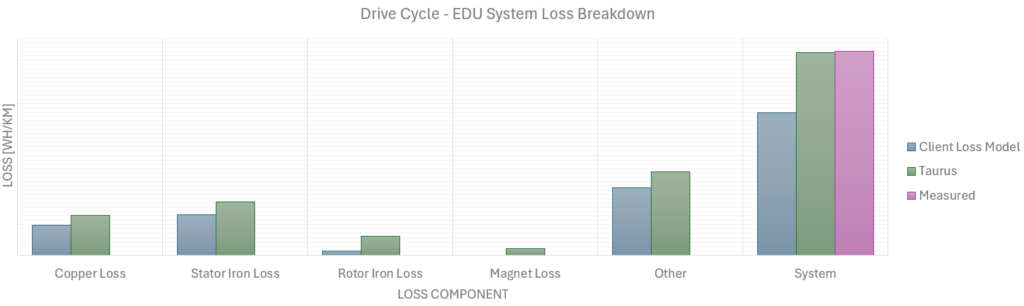
Underestimated PWM-induced copper, iron and magnet losses accounted for about 75% of the gap to the measurements.
03
The result
About three quarters of the missing losses turned out to be PWM-induced: losses the original model did not account for. With the root cause identified, the customer got a concrete optimisation path, and a model they can trust for cooling sizing, switching-frequency maps and PWM strategy.
Why it matters beyond this case
Design decisions are only as good as the loss model behind them. That’s why we put accurate loss models, including PWM effects, at the start of every motor and driveline study, not at the end.